Showing posts with label #autolisp #cad #ptcad. Show all posts

Wednesday, February 18, 2026

FREE LISP : Draw Stair Number

Auto Numbering Along a Line in PTCAD (Using LISP)

When working with drawings such as layout grids, parking numbers, seat numbers, column numbering, or coordinate markers, we often need to place numbers evenly spaced along a straight line. Doing this manually can be slow and error-prone.

This simple LISP routine helps automate the process.

What This LISP Does

The command allows the user to:

  1. Specify the number of texts

  2. Define the starting number

  3. Set the text height

  4. Pick a start point and end point

The program will then:

  • Place the first number at the start point

  • Place the last number at the end point

  • Automatically divide the space evenly

  • Insert all numbers in sequence

Example result:

1 ---- 2 ---- 3 ---- 4 ---- 5

All numbers are spaced equally along the selected line.

Why This Is Useful

This tool is especially helpful for tasks such as:

  • Column numbering in structural drawings

  • Parking lot numbering

  • Seat numbering in halls or stadiums

  • Grid labeling

  • Survey or coordinate markers

  • Repetitive annotation tasks

Instead of calculating spacing manually, the LISP automatically divides the distance and places the numbers correctly.

Tips for Best Use

Use Object Snap (OSNAP)
Snap precisely to the intended start and end points.

Use appropriate text height
Choose a height that matches the drawing scale.

Plan the numbering direction
Numbers will increase from the first picked point toward the second point.

Use it with construction lines
You can draw a temporary line as a guide and erase it afterward.

Works in all CAD version support LISP
Because the routine uses standard LISP (no Visual LISP functions).

Productivity Benefit

For example:

Manual work

Place text → copy → move → edit numbers → repeat

Using this LISP

Pick start → pick end → done

                 What might take 2–3 minutes manually can be done in just a few seconds.


Here is VDO Link

https://www.tiktok.com/@ptcaduser/video/7613673564130086160?is_from_webapp=1&sender_device=pc&web_id=7486330426983859719


Below is source code.

Command to run  is NLL


(defun c:NLL (/ p1 p2 n startnum hgt i dx dy px py)
  (setq n (getint "\nNumber of texts: "))
  (setq startnum (getint "\nStarting number: "))
  (setq hgt (getreal "\nText height: "))
  (setq p1 (getpoint "\nPick start point of line: "))
  (setq p2 (getpoint p1 "\nPick end point of line: "))
  (setq dx (/ (- (car p2) (car p1)) (- n 1)))
  (setq dy (/ (- (cadr p2) (cadr p1)) (- n 1)))
  (setq i 0)
  (while (< i n)
    (setq px (+ (car p1) (* i dx)))
    (setq py (+ (cadr p1) (* i dy)))
    (command "TEXT" (list px py) hgt "0" (itoa (+ startnum i)))
    (setq i (+ i 1))
  )
  (princ)
)


Monday, December 1, 2025

Get Ready : PTCAD 2026 is Launching


Announcing the Next Evolution of Reliable and Affordable DWG CAD Software

We are thrilled to announce a major milestone for our community of designers, engineers, and architects: PTCAD 2026 is officially launching on January 15, 2026!

PTCAD has always been committed to providing a powerful, cost-effective, and fully DWG-compatible CAD solution. With the release of PTCAD 2026, we are delivering on that promise by introducing significant performance boosts, smarter tools, and new features designed to streamline your workflow and dramatically enhance your productivity—all without the hefty price tag of traditional CAD subscriptions.


✨ What to Expect in PTCAD 2026

The new version focuses on three core areas: Speed, Intelligence, and Collaboration. Here’s a sneak peek at some of the key enhancements you can look forward to:

1.  Worth in class

We continue to ensure PTCAD is the best alternative for interoperability in a multi-CAD environment. 

  • True DWG Compatibility: PTCAD 2026 fully supports the latest DWG file format, ensuring perfect fidelity when sharing files with users of other leading CAD software.
  • Cost-Effectiveness : PTCAD ensures you get the tools you need for less. This reduction in software costs directly contributes to a stronger bottom line and helps your firm maximize its overall profit margins."

2. Smarter Tools

  • QR Code Support 

    Use the new QRTEXT and QRLEADER commands to embed QR codes directly into drawings—ideal for linking drawings to metadata, contacts, assets, or websites.

  • Enhanced Table and MTEXT Editing  Excel-style auto-fill in tables, new stacking options in MTEXT, and improved editing tools streamline data entry and annotation tasks.
  • UI Features for Power Users Detached drawing windows and command-line transparency options enable advanced workflows across multiple monitors.

  • Asset Link function : A updated tool to manage and link non-CAD asset data (like inventory or maintenance logs) directly to objects within your DWG files.

  • Enhanced AutoLISP Support: For our power users, we've improved AutoLISP compatibility and performance to run your existing custom routines more efficiently.

3. Seamless Collaboration and Compatibility

Leverage your working process. Use new tool for collaborate your work continuously.

  • EDM:  Create professional workflow by using new tool for  drawing proposed for review and approve in secure environment.
  • Drawing Compare Pro: Compare two versions of a drawing with greater detail and efficiency, making it easier to track changes and manage revisions.


🗓️ Mark Your Calendars!

The official launch of PTCAD 2026 is scheduled for January 15, 2026!

Starting on that date, you can download the free 30-day trial or update to new version.

Exclusive Webinar Preview!

Want to see PTCAD 2026 in action before anyone else? Join our free online webinar where our product specialists will take you on a deep dive into all the new features and answer your questions live!

  • Date: January 30, 2026

  • Time: 2pm-4pm (GMT+7)

  • Registration Link:  see update information at https://www.facebook.com/ptcadthai

Wednesday, November 5, 2025

PTCADuser on TIKTOK Channel

Dear  PTCAD blog readers,

        We hope you're having a productive time using PTCAD!

We are thrilled to announce a brand-new way to connect with the team and get quick, engaging tips, tricks, and updates for your favorite design software.

The PTCAD content  is now also on TikTok!

📱 Why Follow Our TikTok?

We've launched our TikTok channel to bring you fast, fun, and highly informative content perfect for designers on the go. You can expect:

  • ⚡ Quick Tips & Tutorials: Short videos demonstrating powerful PTCAD features and hidden gems.

  • 🛠️ Workflow Hacks: Learn efficient ways to speed up your design process.

  • 🤩 Sneak Peeks: Get a first look at new updates, features, and content.

  • 🤝 Community Highlights: See how other users are maximizing PTCAD in their projects.

🔗 Follow Us Now!

Ready to level up your PTCAD skills in just 60 seconds?

Click the link below and hit 'Follow'!

(9)ptcaduser (@ptcaduser) | TikTok

We can't wait to see you there! We encourage you to like, share, and comment on our videos—let us know what quick tutorials you'd like to see next!

Sincerely yours,

PTCADuser team


Wednesday, October 15, 2025

FREELISP : Scale selected object 2 times

         This is shortcut command to scale selected object bigger 2 times refer selected reference clicked point.


        Here is LISP source code :

(defun c:SCALE2X ( / ss basept)
  (prompt "\nSelect objects to scale: ")
  (setq ss (ssget))
  (if ss
    (progn
      (prompt "\nSpecify base point: ")
      (setq basept (getpoint "\nPick base point: "))
      (if basept
        (progn
          (command "_.SCALE" ss "" basept "2")
          (prompt "\nObjects scaled by 2×.")
        )
        (prompt "\nBase point not selected.")
      )
    )
    (prompt "\nNo objects selected.")
  )
  (princ)
)

command is SCALE2x

--------------
Tip : user can adjust scale size by changing number in this line in source code

          (command "_.SCALE" ss "" basept "2")


Sunday, April 27, 2025

FREELISP : Align circles in x or y axis


            If user want to make group of circles  align with reference one in X-axis or Y-axis.  Pls download LISP source code and run in your PTCAD.  Video below show how to use command (axy).

    Here is Video


@ptcaduser

PTCAD-align clrcles #cad #ptcad #aligncircle #autolisp #lsp #acad

♬ original sound - ptcaduser


Here is LISP source code  

(defun c:Axy( / refEnt refData refCenter selSet idx entData mode moveVec srcCenter )
  
  ;; Select reference circle
  (setq refEnt (car (entsel "\nSelect reference circle: ")))
  (if (and refEnt (eq (cdr (assoc 0 (entget refEnt))) "CIRCLE"))
    (progn
      (setq refData (entget refEnt))
      (setq refCenter (cdr (assoc 10 refData)))
      ;; Ask user alignment axis
      (initget "X Y")
      (setq mode (getkword "\nAlign by [X/Y]: "))
      ;; Select circles to align
      (setq selSet (ssget '((0 . "CIRCLE"))))
      (if selSet
        (progn
          (setq idx 0)
          (while (< idx (sslength selSet))
            (setq ent (ssname selSet idx))
            (setq entData (entget ent))
            (setq srcCenter (cdr (assoc 10 entData)))
            
            (cond
              ;; Align X axis only
              ((= mode "X")
               (setq moveVec (list (- (car refCenter) (car srcCenter)) 0.0 0.0))
              )
              ;; Align Y axis only
              ((= mode "Y")
               (setq moveVec (list 0.0 (- (cadr refCenter) (cadr srcCenter)) 0.0))
              )
            )
            ;; Move the circle
            (command "MOVE" ent "" '(0 0 0) moveVec)
            (setq idx (1+ idx))
          )
          (princ "\n✅ Circles aligned successfully.")
        )
        (princ "\nNo circles selected.")
      )
    )
    (princ "\n❌ Please select a valid circle as reference.")
  )
  (princ)
)

Tuesday, January 7, 2025

Free LISP : LISP commands to work faster in 3D

LISP commands to work faster in 3D


     Here are some LISP program created short cut commands to help user work faster in 3D mode.


VIEW MODE

This LISP program to create short command to change current view to be ISOMETRIC view

(defun c:viso ()

  (command "._viewpoint" "1,-1,1" "")

)


CREATE MODE

  • EXTRUDE multiple closed polyline

(defun c:ex1 ( / ss i ent height )


  (setq ss (ssget '((0 . "LWPOLYLINE")))) ; Select closed polyline
  (if ss
    (progn
      (setq height (getreal "\n Height to Extrude: "))
      (setq i 0)
      (while (< i (sslength ss))
        (setq ent (ssname ss i))
             (command "_FMEXTRUDE" ent "" height)


        (setq i (1+ i))
      )
    )
    (princ "\n no closed polyline selected")
  )
)

  • Create ROOF GABLE from closed polyline
; command is GB1
(defun midpoint (p1 p2)

  (mapcar '(lambda (a b) (/ (+ a b) 2.0)) p1 p2)
)

(defun raise-point (pt h)
  (list (car pt) (cadr pt) (+ (caddr pt) h))
)

(defun ensure-3d (pt)
  (if (= (length pt) 2)
    (append pt (list 0.0))
    pt
  )
)

(defun distance-3d (p1 p2)
  (distance p1 p2)
)

(defun Mid4P (  pt1 pt2 pt3 pt4 / cx cy )
 ; (prompt "\nSelect 4 points:")
  ;(setq pt1 (getpoint "\nPoint 1: "))
 ; (setq pt2 (getpoint "\nPoint 2: "))
 ; (setq pt3 (getpoint "\nPoint 3: "))
 ; (setq pt4 (getpoint "\nPoint 4: "))

  ;; find center point 
  (setq cx (/ (+ (car pt1) (car pt2) (car pt3) (car pt4)) 4.0))
  (setq cy (/ (+ (cadr pt1) (cadr pt2) (cadr pt3) (cadr pt4)) 4.0))
  (setq center (list cx cy))

)


(defun c:GB1 ( / ent elst pts p1 p2 p3 p4 ridge1 ridge2 h len1 len2 ridgeMid1 ridgeMid2 center )

  (setq ent (car (entsel "\nSelect closed 4-sided polyline: ")))
  (setq elst (entget ent))

  (if (and ent (= (cdr (assoc 0 elst)) "LWPOLYLINE"))
    (progn
      ;; Extract 4 vertices
      (setq pts '())
      (foreach item elst
        (if (= (car item) 10)
          (setq pts (append pts (list (ensure-3d (cdr item)))))
        )
      )
      (if (= (length pts) 4)
        (progn
          (setq p1 (nth 0 pts)
                p2 (nth 1 pts)
                p3 (nth 2 pts)
                p4 (nth 3 pts))

          ;; Ask user for roof height
          (setq h (getreal "\nEnter roof height (slope): "))

          ;; Measure lengths of two opposing sides
          (setq len1 (distance-3d p1 p2)) ; side 1-2 vs 3-4
          (setq len2 (distance-3d p2 p3)) ; side 2-3 vs 4-1

          ;; Determine ridge direction: along the shorter opposing side
          (if (< len1 len2)
            (progn
              (setq ridgeMid1 (midpoint p1 p2))
              (setq ridgeMid2 (midpoint p3 p4))
         (setq ridge1 (raise-point ridgeMid1 h))
          (setq ridge2 (raise-point ridgeMid2 h))
          (command "3DFACE" p1 p2 ridge1 ridge1 "")
          (command "3DFACE" p2 p3 ridge2 ridge1 "")
          (command "3DFACE" p3 p4 ridge2 ridge2 "")
          (command "3DFACE" p4 p1 ridge1 ridge2 "")
            )
            (progn
              (setq ridgeMid1 (midpoint p2 p3))
              (setq ridgeMid2 (midpoint p4 p1))
         (setq ridge1 (raise-point ridgeMid1 h))
          (setq ridge2 (raise-point ridgeMid2 h))
          (command "3DFACE" p1 p2 ridge1 ridge2 "")
          (command "3DFACE" p2 p3 ridge1 ridge1 "")
          (command "3DFACE" p3 p4 ridge2 ridge1 "")
          (command "3DFACE" p4 p1 ridge2 ridge2 "")
            )
          )

          ;; Raise ridge points
          (setq ridge1 (raise-point ridgeMid1 h))
          (setq ridge2 (raise-point ridgeMid2 h))


          (princ "\n Gable roof created from 4-sided polyline.")
        )
        (princ "\nPolyline must have exactly 4 vertices.")
      )
    )
    (princ "\nInvalid selection. Please select a closed 4-sided polyline.")
  )
  (princ)
)


Tuesday, December 17, 2024

FREE LISP : Numbering with Circle


FREE LISP: Automatic Numbering with Circle (NUMCIR)

Introduction

In professional CAD drafting—especially in architectural, structural, and engineering drawings—numbered callouts inside circles (bubble tags) are widely used. These are essential for identifying details, sections, columns, reference points, and annotations.

Manually drawing a circle and placing text for each item is repetitive, time-consuming, and prone to inconsistency. To address this, we developed an AutoLISP tool called NUMCIR, which automates the entire process.


What is NUMCIR?

NUMCIR is an LISP command that allows users to:

  • Automatically generate sequential numbers (1, 2, 3, …)

  • Place them interactively by clicking in the drawing

  • Create a circle around each number

  • Continue placing until pressing Enter to finish

This tool is ideal for creating clean and consistent callouts quickly.


How It Works

The logic behind NUMCIR is simple and efficient:

  1. Initialize a counter starting at 1

  2. Ask the user to input text height

  3. Calculate circle radius based on text height

  4. Enter a loop:

    • Wait for the user to pick a point

    • Place centered text at that point

    • Draw a circle around the text

    • Increment the number

  5. Exit when the user presses Enter

How to Use

  1. Load the LISP file using APPLOAD

  2. Type command: NUMCIR

  3. Enter desired text height

  4. Click locations in the drawing

  5. Each click creates a number inside a circle

  6. Press Enter to finish


Practical Applications

This tool is highly useful in:

  • Architectural drawings
    Detail callouts, room tags, section markers

  • Structural drawings
    Column numbering, footing references

  • MEP drawings
    Equipment tags, system references

  • Shop drawings
    Part identification and labeling


Advantages

  • ✅ Speeds up repetitive annotation tasks

  • ✅ Ensures consistent size and alignment

  • ✅ Reduces manual drafting errors


Source code

(defun c:NUMCIR ( / pt num hgt rad )
  
  (setq num 1) ; start number
  (setq hgt (getreal "\nEnter text height: "))
  (setq rad (* hgt 1.2)) ; circle radius
  
  (while (setq pt (getpoint "\nPick point to place (Enter to stop): "))
    
    ;; Create centered TEXT
    (command "TEXT" "J" "MC" pt hgt 0 (itoa num))
    
    ;; Create CIRCLE
    (command "CIRCLE" pt rad)
    
    (setq num (+ num 1))
  )
  
  (princ)
)


Wednesday, May 22, 2024

Custom Short Commands for Speed

 Custom Short Commands for Speed


PTCAD supports the creation of custom short commands using 1 or 2 characters, allowing users to quickly access commands without having to type the full command name. For example, L stands for Line, and C stands for Circle.

To create your own shortcut commands, users can go to the shortcut command settings by

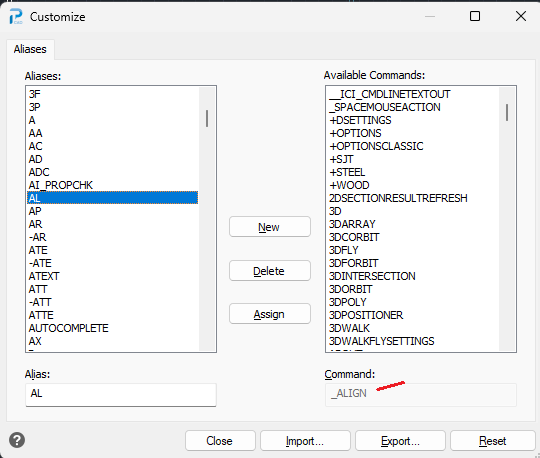
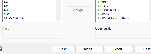
typing the command ALIASEDIT and pressing Enter. This will open a dialog box as shown below.


On the left side, you will see the existing aliases (shortcuts), and on the right side, you will see the full command names. For example, clicking on AL reveals that it is the alias for the ALIGN command.

In this example, we’ll create two custom shortcuts for users who frequently work in 3D and often need to switch views between the Top View and the Isometric View.


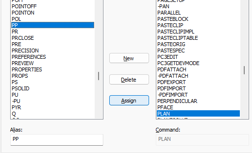
  1. We will assign the alias PP to the PLAN command.

1.1 Click the New button, then type PP into the Alias field in the lower-left corner.

1.2 On the right-hand side, search for the PLAN command, click it so it turns blue, then click the Assign button as shown below.


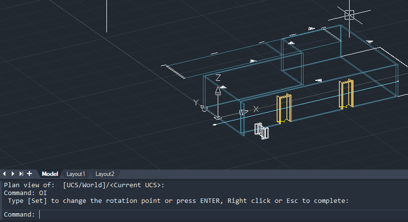
  1. Next, we’ll assign the alias Oi to the 3DORBIT command by repeating the same steps as in item 1.

The 3DORBIT command allows you to switch to a 3D view.


Try using the Oi command, then click and hold the left mouse button to change the view in real-time.


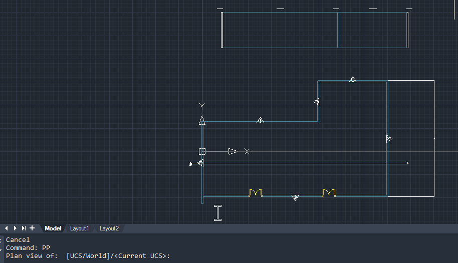
Now try using the PP command and press Enter twice — the view will instantly switch back to Top View.


For users who prefer typing commands in the command line, shortcut aliases can greatly help save time and improve workflow efficiency.

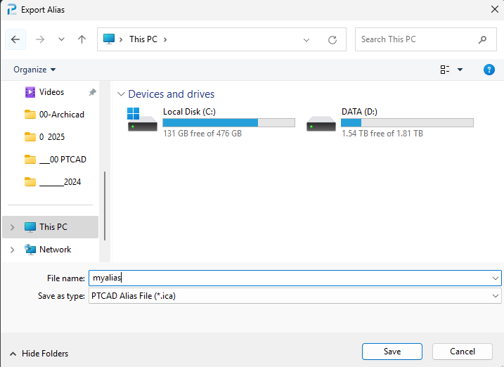
Additionally, once you’ve set up a number of aliases, you can export your shortcut set into a file with the .ica extension for backup or transfer.


Tuesday, April 2, 2024

20 Keyboard Commands Available in PTCAD

 20 Keyboard Commands Available in PTCAD

In PTCAD, users can execute commands using keyboard shortcuts as follows:

  • F1 – Opens the Help window

  • F2 – Opens the Command Prompt window to view command history

  • F3 – Toggles Entity Snap on/off (e.g., snap to endpoint, midpoint, center, etc.)

  • F5 – Switches Isometric drawing planes

  • F7 – Toggles Grid Display on/off

  • F8 – Toggles Ortho Mode on/off (locks movement along X or Y axis)

  • F9 – Toggles Snap Mode on/off

  • Ctrl + A – Selects all objects in the drawing

  • Ctrl + C – Copies selected objects

  • Ctrl + X – Cuts selected objects for pasting elsewhere

  • Ctrl + V – Pastes copied/cut objects and lets you specify an insertion point

  • Ctrl + Z – Undoes the last command

  • Ctrl + Y – Redoes the last undone command

  • Ctrl + S – Saves the current drawing

  • Ctrl + 1 – Opens/closes the Properties Palette

  • Ctrl + 2 – Opens/closes the PTCAD Explorer Palette

  • Ctrl + 3 – Opens/closes the Tool Palette

  • Ctrl + 4 – Opens/closes the Sheet Set Manager

  • Ctrl + 5 – Opens/closes the Selection Filter Palette

  • Ctrl + Shift – Activates the 3DORBIT mode

    • With Left Mouse Button – Zoom in/out

    • With Middle Mouse Button – Rotate the 3D view


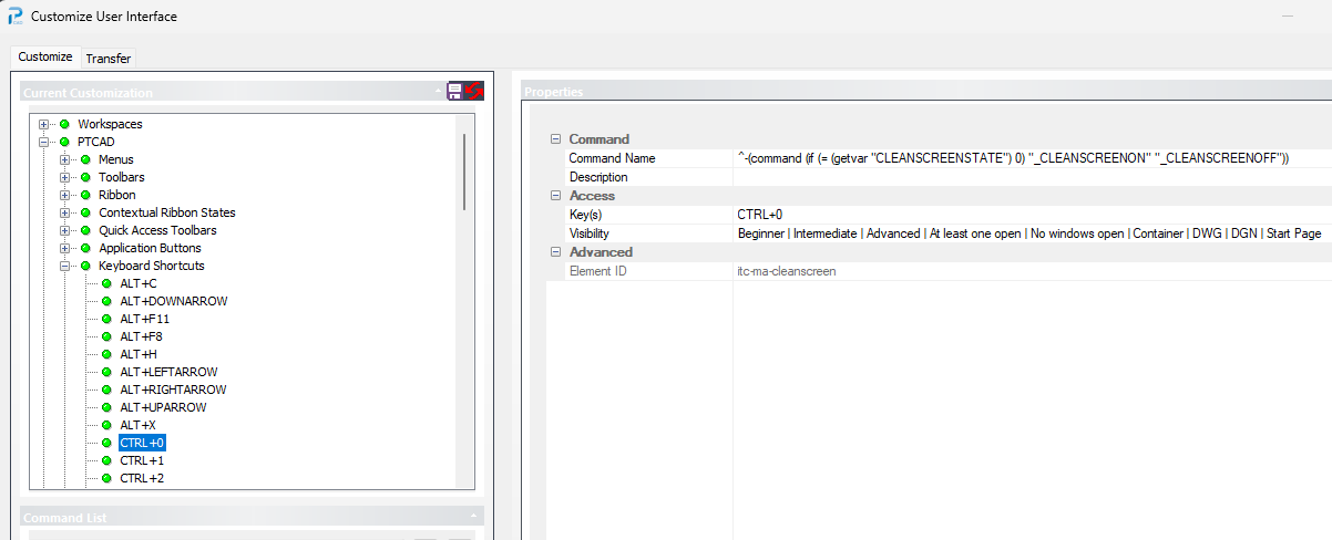
These shortcut commands can be customized or reassigned by users through the CUI command, which opens the Customize User Interface window.
To modify or create new commands, further learning on command scripting may be required


FREE LISP : Improving Drawing Quality by using Ortho-Check LISP

  Improving Drawing Quality with an Ortho-Check LISP Tool In many CAD workflows, especially in architectural, engineering, and construction...